
Learning how to install LED track light fixtures properly is essential when mismatched rail adapters and dark commercial displays threaten your project schedule. Dead fittings and loose connections on site quickly erode contractor profit margins and damage client trust. Mastering the physical and electrical matching process upfront prevents costly rework and delivers clean, reliable illumination across every commercial zone.
To install LED track light fixtures, first shut off mains power and confirm track adapter compatibility. Align the adapter polarity guide with the track groove, insert the contact housing firmly into the channel, and rotate the mechanical locking lever 90 degrees. Turn the circuit selector to the designated line, restore power, test illumination, and adjust beam aiming.
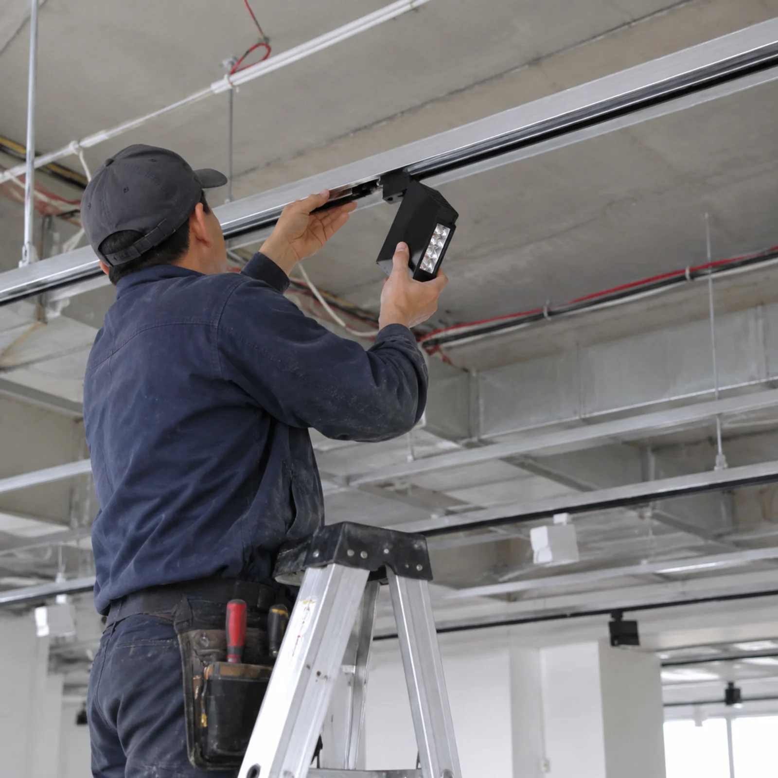
Many contractors assume all commercial track heads snap together identically. In our factory assembly lines and testing benches, I regularly observe that physical fit does not guarantee electrical continuity. Let us examine the critical compatibility rules, step-by-step mechanical mounting practices, and diagnostic procedures required for a dependable installation.
Why Must You Check Track Compatibility Before You Install LED Track Light Fixtures?
Ordering track heads that fail to seat inside existing ceiling rails creates immediate job-site delays and unexpected return freight costs. Forcing an incompatible adapter into a track channel can crack the polycarbonate casing and distort the internal copper conductors. A brief pre-installation compatibility review safeguards your project budget, luminaire electronics, and architectural surfaces.
You must verify track compatibility before installation because rail dimensions, busbar positions, and conductor counts vary across international standards. A 3-circuit European adapter cannot fit inside a single-circuit North American rail. Matching the specific adapter profile, rail system, operating voltage, and dimming protocol ensures mechanical retention, electrical safety, and stable lighting performance.
Understanding Regional Track Standards and Busbars
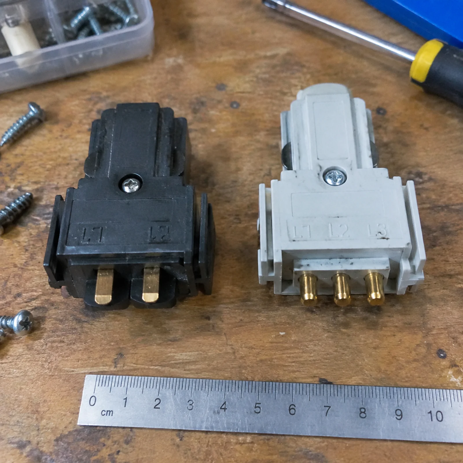
Track lighting is not a universal plug-and-play category. Different countries and legacy manufacturers use proprietary rail profiles. When commercial clients send me photos of lights that "refuse to click in," the root cause is almost always a profile mismatch between the adapter foot and the internal track geometry.
In North America, three legacy standards dominate the line-voltage market:
- H-Type (3-wire / 1-circuit): Features two flat contact blades on one side and a single ground wire contact on the other.1
- J-Type (2-wire or 3-wire): Features contact blades spaced differently, often with a flared grounding prong.
- L-Type (2-wire or 3-wire): Utilizes distinct contact heights and proprietary locking clips.
In Europe, the Middle East, and parts of Asia, the commercial sector predominantly relies on 3-phase / 4-wire (often called Eurotrack) systems. These rails contain three separate live busbars and one neutral busbar. They allow users to switch three distinct lighting circuits on a single continuous rail run.2
| Track System Standard | Conductor Count | Circuits Available | Common Regions | Dimming Integration |
|---|---|---|---|---|
| H-Style Track | 3 Conductor | 1 Circuit | North America | Phase-cut (TRIAC/ELV) |
| J-Style Track | 2 or 3 Conductor | 1 Circuit | North America | Phase-cut (TRIAC/ELV) |
| 3-Phase Eurotrack | 4 Conductor | 3 Separate Circuits | Europe, Middle East, Asia | Phase-cut / Analog |
| DALI / 3-Phase Track | 6 Conductor | 3 Power + 2 Control | Global Commercial | DALI, DMX, 0-10V |
| Low-Voltage Magnetic | 2 to 4 Conductor | 1 Circuit (48V DC) | High-End Residential, Retail | DALI, Zigbee, 0-10V |
Mechanical Keying and Polarity Ridges
Every quality track system incorporates a mechanical polarity ridge or asymmetrical groove running along one side of the rail interior. The luminaire adapter features a matching guide rib.
During our assembly and quality-control fitting trials, I consistently remind our assembly technicians never to force an adapter into a rail. If the adapter does not slide inward smoothly with gentle hand pressure, the adapter is oriented 180 degrees backward. Forcing the unit backward shears off the alignment tab. It can also cause an immediate short circuit by driving the live contact pin directly into the neutral busbar.3
Electrical and Dimming System Alignment
Mechanical fit is only step one. You must verify that the driver housed inside the track light bracket matches the site supply voltage and control architecture.
- Supply Voltage and Frequency: Verify whether your project site runs on 100–120V at 60Hz or 220–240V at 50Hz. Universal drivers (100–277V) provide flexibility, but dedicated-voltage drivers require strict supply checks.
- Control Protocol: Standard phase-cut (TRIAC) dimming works over standard power lines. However, digital protocols like DALI require dedicated data busbars inside a 6-conductor track.4 Connecting a standard 3-phase adapter to a DALI-controlled rail leaves the light head operating at fixed output or produces unstable flickering.
Before signing off on large purchase orders, obtain mechanical engineering drawings of the existing track profile and share them directly with your luminaire manufacturer.
How to Install LED Track Light Heads Step by Step?
Scratched ceiling rails, cracked adapter housings, and damaged contact pins occur when installers rush overhead work without standard procedures. Overhead physical fatigue increases the risk of dropping expensive fixtures onto commercial showroom floors. Adhering to a standardized, methodical installation workflow ensures secure mechanical latching, protects internal drivers, and keeps job sites accident-free.
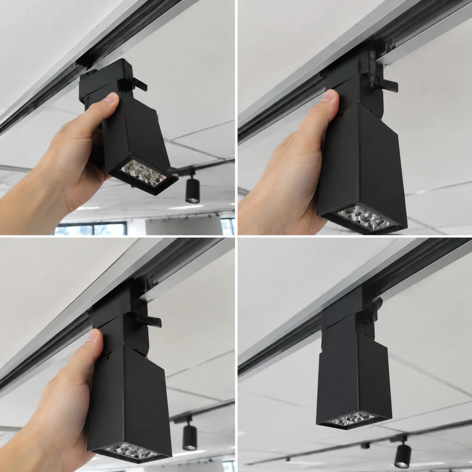
Install the light head by isolating electrical power at the distribution board, checking the adapter alignment against the track groove, and pushing the base firmly into the rail channel. Turn the mechanical locking lever 90 degrees to clamp the fixture, dial the phase selector to your target circuit, restore mains power, and adjust your optical aiming.
Step 1: Isolate Power and Verify the Circuit
Safety takes precedence on every commercial installation. Never insert or extract track heads from an energized track rail.
- Shut off the dedicated lighting circuit breaker at the distribution board.
- Apply a lockout/tagout device to prevent accidental re-energizing by other trades on site.5
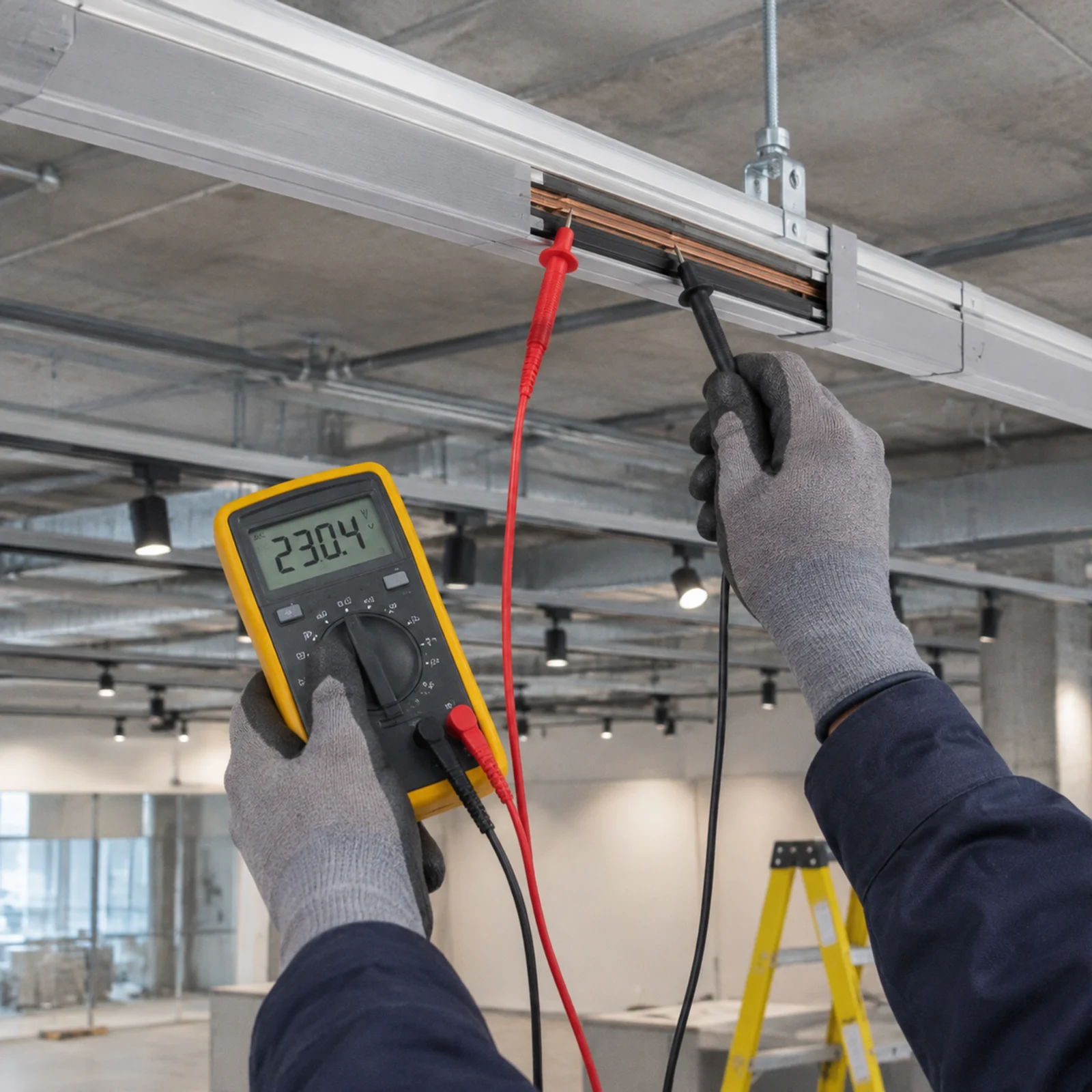
- Use a certified non-contact voltage tester or a calibrated digital multimeter inside the track channel to confirm zero voltage between all live conductors, neutral, and ground.
Arcless insertion preserves the delicate gold-plated or nickel-plated contact shims of the adapter. Inserting fixtures into energized tracks generates micro-arcing. Over time, micro-arcing pits the copper track busbars and leads to high-resistance electrical connections.6
Step 2: Inspect Adapter Orientation and Mechanical Alignment
Examine the track adapter on your luminaire before climbing the ladder or mobile scaffold platform.
- Locate the Polarity Groove: Find the longitudinal groove on the exterior extrusion of the ceiling rail.
- Find the Guide Tab: Locate the raised plastic tooth on the track light adapter body.
- Retract the Contacts: Ensure the mechanical lock lever is completely in the "Open" or "Unlocked" position. On multi-circuit adapters, make sure the circuit selector dial is set to "0" or "OFF" so internal contact copper leaves remain retracted inside the plastic housing.
Step 3: Insert the Adapter and Engage the Mechanical Lock
Support the die-cast aluminum housing of the fixture with one hand while holding the adapter base with the other.
- Push the adapter housing vertically upward into the track channel. It must sit flush against the rail opening with zero visible tilt.
- While applying steady upward pressure, rotate the primary mechanical locking lever 90 degrees until it clicks into the locked detent.
- You should feel positive resistance as the internal cams engage the aluminum lips of the track rail. This lock supports the entire physical weight of the fixture. If the lever feels loose or jams before reaching 90 degrees, pull the fixture straight down, recheck the polarity tab alignment, and try again.
[Track Rail Interior]
  |  (Live Busbar)   (Neutral Busbar)  |
  |      [==]              [==]        |
  |                                    |
  +---[ Adapter Enters Straight ]------+
          |                  |
      [Contact Pin]      [Contact Pin]
          |                  |
   [Rotate Mechanical Lever 90 Degrees]
Step 4: Select the Electrical Circuit
For multi-phase commercial tracks (such as 3-phase European rails), the adapter features a rotary switch knob labeled 0, 1, 2, and 3.
- Turn the rotary dial to the designated circuit number specified in your lighting design plans.
- Rotating the dial pushes internal copper contact pins laterally outward to touch the specific live busbar inside the rail.
- For single-circuit tracks, this step is handled automatically by the main locking lever.
Step 5: Power-On Testing and Optical Aiming
Restore power at the breaker panel once all luminaires are mechanically latched and assigned to their respective circuits.
- Confirm that every luminaire illuminates immediately without strobing or buzzing.
- Loosen the horizontal and vertical locking screws on the fixture mounting bracket slightly if your model uses manual friction locks.
- Aim the optical head toward the target display wall, merchandise rack, or architectural accent.
- Tighten the locking screws to prevent thermal drift over thousands of operational hours.7 Never twist the optical head beyond its designated rotation stops; excessive rotation twists and severs internal primary wiring.
In our production testing facility, every unit undergoes full functional testing and high-temperature aging before packing. When a fixture fails to illuminate immediately after on-site insertion, the issue is almost never an unvetted component failure. It is almost always a contact misengagement.
How Do You Troubleshoot Issues After You Install LED Track Light Heads?
Discovering that a newly mounted fixture remains dark or flickers erratically can lead to frustration and project delays. Installers often assume the LED driver or COB chip is defective and initiate unnecessary product returns. In commercial projects, post-installation failures stem primarily from misaligned contact pins, incorrect phase selection, or dimmer incompatibilities rather than factory defects.
When a fixture fails to light up or flickers after installation, check that the mechanical lock has fully rotated to project the contact shims outward. Confirm that the phase selector dial matches an energized live circuit, test track busbar voltage with a multimeter, and verify that your phase-cut or digital dimmer matches driver specifications.
Systematic Problem Isolation
Before unmounting fixtures and filing warranty claims, follow a disciplined diagnostic routine. I always recommend isolating the variable by testing the non-responsive fixture in a known-working track section.
[Fixture Does Not Illuminate]
             │
   Is mechanical lock fully engaged?
   ├── NO  ──> Rotate locking lever 90° until it clicks flush.
   └── YES ──> Check circuit selection dial.
                    │
   Is phase dial set to energized circuit?
   ├── NO  ──> Switch dial to active phase (1, 2, or 3).
   └── YES ──> Test track rail with multimeter.
                    │
   Is correct voltage present at busbars?
   ├── NO  ──> Check breaker, wall switch, and track feeder wiring.
   └── YES ──> Move fixture to a known working track segment.
                    │
   Does fixture work in the new location?
   ├── YES ──> Original track section has damaged busbar or dead dimmer.
   └── NO  ──> Contact supplier to inspect driver or luminaire internals.
Analyzing Common Field Symptoms
Evaluating field reports and troubleshooting videos from overseas contractors shows that installation errors follow clear patterns. Use the diagnostic matrix below to quickly pinpoint the root cause on site:
| Symptom | Probable Root Cause | Corrective Action |
|---|---|---|
| No illumination | Phase selector set to inactive circuit | Rotate adapter selector dial to Phase 1, 2, or 3. |
| No illumination | Adapter installed in reverse polarity | Disengage lock, reverse adapter 180 degrees, and reseat. |
| No illumination | Contact copper blade bent inward | Isolate power, remove fixture, and inspect adapter pins. |
| Rapid, strobe-like flickering | Dimmer minimum load not met8 | Check dimmer load limits; add luminaires or install an LED load bypass. |
| Flickering when dimming | Incompatible dimmer curve (Leading vs. Trailing) | Replace forward-phase TRIAC dimmer with an electronic trailing-edge unit. |
| Audible buzzing sound | Driver inductor vibrating under noisy phase cut9 | Adjust dimmer trim potentiometers or swap to a 0–10V / DALI architecture. |
| Physical drooping or tilt | Adapter cam lock not seated past internal stop | Push adapter firmly upward and turn lock fully to 90 degrees. |
Inspecting Internal Adapter Contacts
A frequent hidden issue occurs when an installer repeatedly forces an adapter into a rail without unlocking the cam. This action pushes the flexible bronze contact shims deep into the adapter housing. When the installer finally locks the unit, the flattened shims cannot bridge the physical gap to reach the copper busbars.
If a fixture fails to turn on in an energized track:
- Isolate track power completely.
- Remove the fixture and examine the bottom contact pins.
- Compare the pin extension height to a brand-new unit from the carton.
- If a pin is bent or compressed flat, contact an electrician or replace the adapter assembly. Never bend contact leaves outward using metallic tools while working on or near an energized track.
Resolving Driver and Dimmer Incompatibilities
Modern commercial LED track lights utilize sensitive constant-current electronic drivers. If your project incorporates wall-mounted dimmers, you must confirm protocol synergy:
- TRIAC / Leading-Edge Dimmers: Designed originally for resistive incandescent filaments. When paired with high-efficiency LED drivers, they often cause strobing at low dimming levels.10
- ELV / Trailing-Edge Dimmers: Produce smoother performance with modern phase-dimmable track drivers.11
- Digital Systems (DALI / 0–10V): Require proper polarity on the low-voltage control lines. Reversing the D+ and D- control wires on a DALI rail freezes the luminaires at 100% brightness or forces them into emergency recovery mode.
Systematic troubleshooting prevents the premature labeling of luminaires as defective and helps keep client handovers on schedule.
Frequently Asked Questions
Can I install any LED track light head on an existing track rail?
No. Track systems feature distinct physical extrusions, conductor counts, and busbar alignments. A luminaire adapter designed for an H-style rail will not fit into a J-style, L-style, or European 3-phase rail. Always check adapter specifications against your existing track brand before purchase.
What is the primary difference between 1-circuit and 3-circuit track lighting?
A 1-circuit track controls every luminaire on the rail simultaneously with a single switch or dimmer. A 3-circuit track contains four conductors (three live lines and one shared neutral), allowing you to split fixtures across three distinct switches on a single ceiling rail.
Do I need an electrician to install LED track light fixtures?
Yes. Installing or modifying track rails, connecting power supply feeds, and making mains-voltage connections require a licensed electrical professional to ensure compliance with local electrical safety codes.12 However, once the track system is safely installed and de-energized, fitting compatible light heads is straightforward.
Why does my LED track light buzz or flicker after installation?
Flickering and buzzing typically indicate an incompatible dimmer switch, an electrical load below the dimmer's minimum wattage threshold, or a loose electrical connection within the adapter. Verify that your dimmer type matches your LED driver and that all adapter contact locks are fully engaged.
Conclusion
Successfully learning how to install LED track light fixtures requires matching adapter profiles, confirming voltage standards, following disciplined overhead mounting practices, and applying methodical troubleshooting diagnostics. Taking the time to verify track busbar compatibility, mechanical keying, and dimming architecture prevents job-site delays, component damage, and project rework.
For overseas lighting contractors, designers, and brand distributors, reliable track lighting performance begins at the manufacturing level. At Shenzhen Jieshida Photoelectric Technology Co., Ltd., we engineer commercial indoor LED track lights using proprietary private die-cast molds for superior thermal management and structural precision. Every luminaire undergoes 100% full inspection and high-temperature aging before dispatch. We back every order with pre-shipment testing videos, full parameter customization, and flexible low-MOQ sample runs. Contact our technical engineering team today to review track compatibility for your upcoming commercial installation.
"HALO | Track Lighting", https://www.cooperlighting.com/global/brands/halo/track. Industry technical reference manuals document H-type track as a 3-wire single-circuit standard originally developed by Halo Lighting, defined by dual parallel power contacts and an opposing grounding blade. Evidence role: historical_context; source type: encyclopedia. Supports: H-style track architecture originates from Halo Lighting specifications utilizing a 3-wire single-circuit configuration with asymmetric contact spacing.. ↩
"IEC 60570:2003", https://webstore.iec.ch/en/publication/2513. International standard IEC/EN 60570 categorizes multi-circuit luminaire supply tracks, codifying four-conductor systems with three discrete live busbars and one neutral line for commercial installations. Evidence role: definition; source type: institution. Supports: International standard IEC/EN 60570 defines four-conductor track geometries that support three independently switched phases with a shared neutral.. ↩
"Track lighting problems", https://www.doityourself.com/forum/lighting-light-fixtures-ceiling-exhaust-fans/507274-track-lighting-problems.html. Safety benchmarks under UL 1574 and IEC 60570 require mechanical polarization keying specifically to avert component shearing and inadvertent live-to-neutral shorting during fixture engagement. Evidence role: mechanism; source type: institution. Supports: Polarity ridges on luminaire tracks physically prevent contact misalignment that would bridge live and neutral lines.. ↩
"Digital Addressable Lighting Interface", https://en.wikipedia.org/wiki/Digital_Addressable_Lighting_Interface. Technical specifications aligned with IEC 62386 mandate dedicated, galvanically isolated data lines, which commercial track manufacturers implement as two auxiliary busbars within a six-conductor profile. Evidence role: mechanism; source type: institution. Supports: Integrating DALI communication onto mains lighting track requires two supplementary low-voltage busbars alongside the four power conductors.. Scope note: The physical layout of control busbars may vary between proprietary manufacturer track extrusions. ↩
"1910.147 - The control of hazardous energy (lockout/tagout). - OSHA", http://www.osha.gov/laws-regs/regulations/standardnumber/1910/1910.147. Occupational safety standards including OSHA 29 CFR 1910.147 and NFPA 70E establish that physical lockout/tagout measures are required to guarantee electrical isolation and protect personnel during luminaire servicing. Evidence role: expert_consensus; source type: government. Supports: Lockout/tagout procedures ensure physical isolation of energy sources to prevent unauthorized or accidental circuit re-energization during maintenance.. ↩
"Simulational study of electrical contact degradation under ...", https://www.sciencedirect.com/science/article/abs/pii/S0301679X11001678. Electrical contact research indicates that unmanaged live mating produces discharge arcs that vaporize contact surfaces, forming pits and non-conductive oxide layers that increase electrical contact resistance over time. Evidence role: mechanism; source type: paper. Supports: Electrical arcing during hot-plug engagement causes localized surface vaporization, pitting copper conductors and degrading interface conductivity.. Scope note: The degree of pitting is heavily influenced by the magnitude of luminaire inrush current and instantaneous line voltage phase. ↩
"Methodology for Designing an Optimal Test Stand for Camera ...", https://pmc.ncbi.nlm.nih.gov/articles/PMC9786690/. Mechanical engineering evaluations of high-intensity luminaires demonstrate that operating thermal cycles induce micro-slip and stress relaxation in bracket fasteners, leading to progressive beam deflection unless mechanically locked. Evidence role: mechanism; source type: paper. Supports: Cyclic thermal expansion and contraction loosen friction joints in luminaire positioning assemblies, causing angular drift.. ↩
"Dummy Load for LED lights / eliminate flickering", https://community.ezlo.com/t/dummy-load-for-led-lights-eliminate-flickering/170342. University electrical laboratory coursework on solid-state lighting controls explains that failing to meet the minimum operational load of a phase-angle controller leads to intermittent conduction cycles that manifest as rapid light pulsing. Evidence role: mechanism; source type: education. Supports: Falling below a dimmer's specified minimum wattage prevents the internal switching device from latching reliably, causing cyclic dropout and visible flicker.. ↩
"How to Reduce Noise From Magnetostriction in Magnetic ...", https://resources.altium.com/p/how-reduce-noise-magnetostriction-magnetic-components. Studies on magnetic component acoustics establish that high di/dt current transients in phase-chopped waveforms excite magnetostrictive deformation and coil vibration in power inductors, radiating audible buzzing. Evidence role: mechanism; source type: paper. Supports: Steep voltage edges from phase-cut dimmers induce rapid magnetic flux variations that generate acoustic noise via magnetostriction and Lorentz forces in inductor windings.. ↩
"NEMA SSL-7A and SSL-7B: Improving phase-control ...", https://www.energystar.gov/sites/default/files/asset/document/Ethan_Biery_DimmableLEDWebinarSlides_Aug252016_0.pdf. NEMA SSL 7A documents that conventional TRIAC dimmers rely on continuous holding current provided by resistive filaments; low current draw and reactive input filters in LED drivers cause erratic thyristor shutoff and optical strobing. Evidence role: mechanism; source type: institution. Supports: Forward-phase TRIAC dimmers misfire at low conduction angles when LED driver draw falls below the minimum holding current threshold.. ↩
"D 161 Understanding LED Lamp and Light Dimmer Issues", https://utia.tennessee.edu/publications/wp-content/uploads/sites/269/2023/10/D161.pdf. Power electronics literature shows that trailing-edge (reverse-phase) dimming eliminates the steep dv/dt voltage steps characteristic of leading-edge control, significantly mitigating inrush current surges and acoustic ringing in electronic LED drivers. Evidence role: general_support; source type: paper. Supports: Trailing-edge dimming cuts the AC waveform at zero voltage rather than switching on abruptly, suppressing inrush current spikes in capacitive LED driver circuits.. Scope note: Performance remains dependent on the specific internal bleeder circuitry of individual dimmable driver models. ↩
"(C) Locations Not Permitted - UpCodes", https://up.codes/s/locations-not-permitted. NFPA 70 (National Electrical Code), Article 410, Part VIII outlines structural, grounding, and wiring regulations for lighting track systems, requiring work to be executed in accordance with jurisdictional safety codes governing mains electrical work. Evidence role: expert_consensus; source type: government. Supports: Electrical codes mandate that branch-circuit connections and fixed luminaire track installations comply with formal wiring methods and professional installation standards.. Scope note: Exact licensing thresholds and code adoption revisions differ across international and local administrative jurisdictions. ↩